Spis treści
The ARD+ Knowledge Representation
Author: Grzegorz J. Nalepa and Igor Wojnicki
Version: Draft 2008Q3
ARD+ stands for Attribute Relationship Diagrams. It is aimed to be as the final ARD version for the official HeKatE project (grant).

Introduction
- goal: build a rule-based knowledge base from system specification
- a case of knowledge engineering (KE)
- the KE process is different from the classic software engineering (SE) process
- important difference between SE and KE is that the former tries to model how the system works, while the latter tries to capture and represent what is known about the system
- the KE approach assumes that information about how the system works can be inferred automatically from what is known about the system
Introduction
- in real life the design process support (as a process of building the design) is much more important than just providing means to visualize and construct the design (which is a kind of knowledge snapshot about the system)
- designing is in fact a knowledge-based process, where the design is often considered a structure with procedures needed to build it (it is at least often the case in the SE)
Introduction
- in case of rules, the design stage usually consists in writing actual rules, based on knowledge provided by an expert
- the rules can be expressed in a natural language, this is often the case with informal approaches such as business rules
- using some kind of formalization as early as possible in the design process improves design quality significantly
Introduction
- the next stage is the rule implementation, it is usually targeted at specific rule engine
- some examples of such engines are: CLIPS, Jess, and JBoss Rules (formerly Drools)
- the rule engine enforces a strict syntax on the rule language
- another aspect of the design - in a very broad sense - is a rule encoding, in a machine readable format; in most cases it uses an XML-based representation
- there are some well-established standards for rule markup languages:, e.g. RuleML and notably RIF (see http://www.w3.org/2005/rules)
History and Related Documents
- The original ARD method was first proposed by A. Ligęza in (ali-book) and later on developed and described by G. J. Nalepa and A. Ligęza in (gjn2005:kkio), (ali-book-springer). It was a supportive, and potentially optional, design method for XTT (gjn2005:syssci:xtt). It provided simple means of attribute identification for the XTT method.
- The first version of ARD was applied to simple cases only, and had no practical prototype implementation. The evolution of XTT, as well as larger complexity of systems designed with it, gave motivation for the major rework, and reformulation of ARD, which resulted in the version called ARD+. ARD+ was defined by G. J. Nalepa and I. Wojnicki in (gjn2008flairs-ardformal) and (gjn2008aaia).
Motivation
- primary motivation for this research is an apparent lack of standard prototyping method for rules, that would support the hierarchical and gradual design aspect covering the entire process
- method should be formalized with use of some logic-based calculus in order to allow a formal analysis
- the research presented in this paper is a part of the HeKatE project, that aims at providing an integrated and hierarchical rule design and implementation method for rule-based systems
Motivation
- the actual rule design is carried out with a flexible rule design method called XTT (eXtended Tabular Trees) (gjn2005sysscixtt)
- the method introduces a structured rulebase
- one of the main requirements for the new prototyping method should be the support for XTT
Preliminary Concepts
- the ARD+ method aims at supporting the rule designer at a very general design level, where the conceptualization of the design takes place (gjn2008flairs-ardformal), (gjn2008aaia)
- it is a knowledge-based approach, based on some classic AI methods (norvig)
- ARD+ covers requirements specification stage
- its input is a general systems description in the natural language
- its output is a model capturing knowledge about relationships among attributes describing system properties
- the model is subsequently used in the next design stage, where the actual logical design with rules is carried out
Preliminary Concepts
The main concepts behind ARD+ are:
- attributive logic based on the use of attributes for denoting certain properties in a system (ali-book-springer), ali2007flairs-granular),
- functional dependency is a general relation between two or more attributes (or attribute sets), called „dependent” and „independent”; the relation is such as in order to determine the values of the dependent attributes, the values of the independent ones are needed,
- graph notation provides simple, standard, yet expressive means for knowledge specification, and transformation,
Preliminary Concepts
- visualization is the key concept in the practical design support, provided by this method,
- gradual refinement is the main design approach, where the design is being specified in number of steps, each step being more detailed than the previous one,
- structural transformations are formalized, with well defined syntax and semantics,
- hierarchical model captures all of the subsequent design steps, with no semantic gaps; it holds knowledge about the system on the different abstraction levels (gjn2007iwk),
- knowledge-based approach provides means of the declarative model specification.
Syntax
- the ARD+ method aims at capturing relations between attributes in terms of Attributive Logic (AL)(ali-book-springer),(ali2007flairs-granular),(gjn2008ruleapps)
- based on the use of attributes for expressing knowledge about facts regarding world under consideration
- typical atomic formula (fact) takes the form
A(o) = d, whereAis an attribute,ois an object anddis the current value ofAforo - more complex descriptions take usually the form of conjunctions of such atoms and are omnipresent in the AI literature
Syntax: Attribute
Let there be given the following, pairwise disjoint sets of symbols:
O – a set of object name symbols,
A – a set of attribute names,
D – a set of attribute values (the domains).
An attribute Ai is a function (or partial function) of the form:
Ai:o → Di.
where o ∈ O.
Syntax: Attribute
A generalized attribute  is a function (or partial function) of the form
 Ai:o → 2Di, where 2Di is the family of all the subsets of Di, to let the attribute take more than a single value at a time.
A relaxed attribute definition, regarding a single object can be stated as:
Ai: Ai → Di.
Syntax: Conceptual Attribute
A conceptual attribute A is an attribute describing some general, abstract aspect of the system
to be specified and refined.
Conceptual attribute names are capitalized, e.g.: WaterLevel.
Conceptual attributes are being finalized during the design process, into, possibly multiple, physical attributes, see Def. finalization.
Syntax: Physical Attribute
A physical attribute a is an attribute describing an aspect of the system with its domain defined.
Names of physical attributes are not capitalized, e.g. theWaterLevelInTank1.
By finalization, a physical attribute origins from one or more (indirectly) conceptual attributes, see Def. finalization.
Physical attributes cannot be finalized, they are present in the final rules capturing knowledge about the system.
Syntax: Property
P is a non-empty set of attributes representing knowledge about certain part of the system being designed.
Such attributes describe the property.
Syntax: Simple Property
PS is a property which consists of (is described by) a single attribute.
Syntax: Complex Property
PC is a property which consists of (is described by) multiple attributes.
Syntax: Dependency
A dependency D is an ordered pair of properties
D1,2=[P1, P2],
where P1 is the independent property, and P2 depends functionally on P1.
Syntax: Derivative
V is an ordered pair of properties, such as:
V=[P1, P2],
where P2 is derived from P1 upon transformation.
Syntax: DPD
A Design Process Diagram is a triple
R=[P,D,V] where P is a set of properties, D is a set of dependencies and V is a set of derivatives.
Syntax: ARD+
An Attribute Relationship Diagram
G is a pair
G=[P, D],
where P is a set of properties, and D is a set of dependencies if there is a DPD G=[P,D,V].
Diagram Restrictions
The diagram constitutes a directed graph with possible cycles.
TPH
A Transformation Process History TPH is a pair:
TPH=[P,V] if there is a DPD G=[P,D,V].
The TPH can be expressed as a directed graph with properties being nodes and derivatives being edges.
Transformations
- diagram transformations are one of the core concepts in the ARD+
- they serve as a tool for diagram specification and development
- for the transformation
Tsuch asT: G1 → G2, whereG1andG2are both diagrams, the diagramG2carries more system related knowledge, is more specific and less abstract than theG1 - all of the transformations regard properties
- some transformations are required to specify additional dependencies or introduce new attributes though
- a transformed diagram
G2constitutes a more detailed diagram level
Finalization Transformation
- finalization
TFis a function which transforms a DPDRintoRTFby transforming a simple propertyPSconsisting of a single conceptual attribute into aPnew, where the attribute belonging toPSis substituted by one or more conceptual or physical attributes belonging toP - appropriate dependencies must be transformed as well and a derivative has to be introduced
- it introduces more attributes (more knowledge) regarding particular property
- an interpretation of the substitution is, that new attributes belonging to
Pare more detailed and specific than attributes belonging toPS
Split Transformation
- a split transforms a DPD
RintoRTSby transforming a complex propertyPCinto some number of properties (a set)Pnew; appropriate dependencies and derivatives must be introduced - this transformation introduces new properties and defines functional relationships among them
Attribute Disjunction
- attribute sets belonging to each of the properties
P1 … Prhave to be disjoint
Attribute Matching
- all attributes
PCconsists of have to belong to propertiesP1, … Pr - no new attributes can be introduced for properties
P1 … Pr - such introduction is possible through finalization only (see Def. finalization)
Attribute Pool
- all attributes
PCconsists of have to belong to[P1, … Pr]
Dependency Inheritance
- all dependencies in
DPChave to be covered by dependencies inDnew - if a
PCdepends on some propertyPx(or some property depends on it), such a dependence must be stated (inDnew) regarding at least one of the elements fromPnewandPx
Transformation Limit
- a number of transformations in a single design step is limited to one per property
- it means that a property can be either split or finalized but not both
Refactoring
- during the design process some properties or attributes can be missed or treated as not important, hence not included in the diagram
- refactoring allows to incorporate such artifacts or remove unnecessary ones
- refactoring consists in modifying any of the existing transformations: finalization or split in a particular ARD+ diagram
Finalization
- a Finalization Refactoring consist in adding or removing an attribute, modifying a past finalization transformation
- removing an attribute
Arresults in removing it from all already defined complex properties; if there is a simple property which regards such an attribute, it should be removed then - the Finalization Refactoring with adding an attribute implies that at some point a split has to be performed on a property involving the new attribute; appropriate dependencies between the property which consists of the introduced attribute and other properties have to be stated as well; this constitutes a Split Refactoring
Split
- Split Refactoring regards:
- adding or removing properties upon already defined splits,
- rearranging already defined dependencies.
- Removing a property implies that all other properties that were split from it, even transitionally, have to be removed.
- Adding a property leads to defining its dependencies, between the property and other already defined ones.
Split
- Adjusting dependencies can be based on:
- defining dependencies between the property and other existing properties at the most detailed diagram level, or
- adjusting appropriate past split transformations gradually (at previous diagram levels) to take this new property into consideration.
- In the first case the dependencies are defined for the most detailed diagram level only; since there is a hierarchical design process (see Sec. Hierarchical Model), these changes are taken into consideration at previous levels automatically.
- The second case implies that the designer updates appropriate past splits in a gradual refinement process; stopping this process at more general level than the most detailed one, generates appropriate splits in all more detailed levels automatically.
Semantics
- the semantics of ARD+ will be explained and visualized using a reworked Thermostat example, discussed in (ali-book-springer), (gjn2005:kkio)
- the goal of the system is to set the temperature in the office to the given set-point, based on the current time
Semantics
- a property always consists of a set of attributes, these attributes identify such a property uniquely
- the single most important concept in ARD+ is the concept of the property functional dependency
- in order to evaluate a dependent property, all independent properties have to be evaluated first
- in order to calculate dependent property attribute values, independent properties attribute values have to be calculated first
- property described by
Temperaturedepends on a property described byTime
Semantics
- identifying all possible properties and attributes in a system could be a very complex task
- transformations (see transformation) allow to gradually refine properties, attributes and functional dependencies in the system being designed
- this process ends when all properties are described by physical attributes and all functional dependencies among properties are defined
Semantics
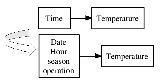
An example of the finalization is given in Figures:
- the top diagram represents the system before the finalization
- the property described by attribute
Timeis finalized - as a result new attributes are introduced:
Date,Hour,season,operation; the outcome is the bottom diagram
Semantics
- semantics of this transformation is that the system property described by a conceptual attribute
Time, can be more adequately described by a set of more detailed attributes:Date,Hour,season,operation, which more precisely define the meaningTimein the design - the two latter attributes are physical ones, used in the final rule implementation
- finalization of properties based on such attributes is not allowed
Semantics
An example of simple finalization is given in Figure:
- a property described by a conceptual attribute Temperature is finalized into a property described by a single physical attribute
thermostat_settings - in other words, a general concept of temperature, represented by
Temperature, is to be represented by an attributethermostat_settings
Semantics
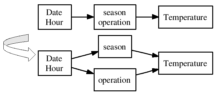
Another ARD+ transformation is the split. An example is given in Figure:
- the top diagram shows a situation before, and the bottom one after, the split transformation
- this split allows to refine new properties and define functional dependencies among them
Semantics
- a property described by attributes:
Date,Hour,season,operation, is split into two properties described byDate,Hour, andseason,operationappropriately - there is a functional dependency defined such as
seasonandoperationdepend onDateandHour
Semantics
During the split, some of the properties can be defined as functionally independent. An example of such a split is given in Figure:
- properties described by
seasonandoperationare functionally independent
Semantics
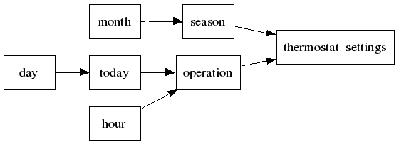
The ARD+ design process based on transformations leads to a diagram representing properties described only by physical attributes.
An example of such a diagram is given in Figure:
- all properties of the designed system are identified
- each of them is described by single physical attribute
- all functional dependencies are defined as well
Semantics
- each transformation creates a more detailed diagram, introducing new attributes (finalization) or defining functional dependencies (split)
- these more detailed diagrams are called levels of detail or just diagram levels
- in the above examples, transitions between two subsequent levels are presented
- a complete model consists of all the levels capturing knowledge about all splits and finalizations
Hierarchical Model
- during the design process, upon splitting and finalization, the ARD+ model grows, becoming more and more specific; this process constitutes the hierarchical model
- consecutive levels make a hierarchy of more and more detailed diagrams describing the designed system
- the purposes of having the hierarchical model are:
- gradual refinement of a designed system, and particularly,
- identification where given properties come from,
- ability to get back to previous diagram levels for refactoring purposes,
- big picture of the designed system.
Hierarchical Model
- the implementation of such hierarchical model is provided through storing the lowest available, most detailed diagram level, and, additionally, information needed to recreate all of the higher levels, so called Transformation Process History, TPH for short (see Def. TPH)
- the TPH captures information about changes made to properties at consecutive diagram levels; these changes are carried out through the transformations: split or finalization
- the TPH forms a tree structure then, denoting what particular properties is split into or what attributes a particular property attribute is finalized into, according to Def. TPH
Hierarchical Model
An example TPH for the transformation is given in Figure:

- it indicates that a property described by an attribute
Timeis refined into a property described by attributes:Date,Hour,season,operation
Hierarchical Model
Another TPH example for the split transformation is given in Figure:
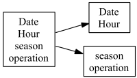
- it indicates that a property described by attributes:
Date,Hour,season,operationis refined into two properties described by:Date,Hourandseason,operationattributes respectively
Hierarchical Model
- having a complete TPH and the most detailed level (namely ARD+), which constitute the DPD (according to Def. DPD) it is possible to automatically recreate any, more general, level
Rule Prototyping Algorithm
- the goal of the algorithm is to automatically build prototypes for rules from the ARD+ design (gjn2008aaia).
- the targeted rule base is structured, grouping rule sets in decision tables with explicit inference control; it is especially suitable for the XTT rule representation
- this approach is more generic, and can be applied to any forward chaining rules
Rule Prototyping Algorithm
- the input of the algorithm is the most detailed ARD+ diagram, that has all of the physical attributes identified (in fact, the algorithm can also be applied to higher level diagrams, generating rules for some parts of the system being designed)
- the output is a set of rule prototypes in a very general format (
attsstands for attributes):
rule: condition atts | decision atts
- the algorithm is reversible, that is having a set of rules in the above format, it is possible to recreate the most detailed level of the ARD+ diagram
Rule Prototyping Algorithm
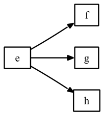
In order to formulate the algorithm some basic subgraphs in the ARD+ structure are considered. These are presented in Figures:
Rule Prototyping Algorithm
Now, considering the ARD+ semantics (functional dependencies among properties), the corresponding rule prototypes are as follows:
- for the case in Figure ard-case0:
rule: e | f, g, h
- for the case in Figure ard-case1:
rule: a, b, c | d
Rule Prototyping Algorithm
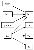
In a general case a subgraph in Figure:
is considered.
- such a subgraph corresponds to the following rule prototype:
rule: alpha, beta, gamma, aa | bb
rule: aa                     | xx, yy, zz
Rule Prototyping Algorithm
Analyzing these cases a general prototyping algorithm has been formulated.
Assuming that a dependency between two properties is formulated as:
D(IndependentProperty,DependentProperty),
the algorithm is as follows:
- choose a dependency
D: D(F,T), F ≠ T, from all dependencies present in the design, - find all properties
F, thatTdepends on:
letFT = [FTi: D(FTi,T), FTi ≠ F], - find all properties which depend on
FandFalone:
letTF=[TFi: D(F,TFi), TFi ≠ T, ¬∃ TFi: (D(X,TFi), X ≠ F )]
Rule Prototyping Algorithm
- if
FT ≠ ∅, TF ≠ ∅then generate rule prototypes:
rule: F, FT1, FT2,... | T
rule: F               | TF1, TF2,...
- if
FT = ∅, TF ≠ ∅then generate rule prototypes:
rule: F | T, TF1, TF2,...
- if
FT ≠ ∅, TF = ∅then generate rule prototypes:
rule: F, FT1, FT2,... | T
- if
FT = ∅, TF = ∅then generate rule prototypes:
rule: F | T
- if there are any dependencies left goto step 1.
Rule Prototyping Algorithm
- rule prototypes generated by the above algorithm can be further optimized
- if there are rules with the same condition attributes they can be merged; if there are rules with the same decision attributes they can be merged
- for instance, rules like:
rule: a, b | x ; rule: a, b | ycan be merged into a single rule:rule: a, b | x, y - the practical support form the ARD+ design method, including logical modelling, visualization, and the prototyping algorithm has been implemented in the VARDA
